1.
PREPARE AutoCAD Consultant Engineering Standards
- SETUP text size, scales, plot styles, layers, labels
- QMS. Folder Love. (Schedules, Standards, Organizing)
- TIDBITS shortcuts
- BLOCKS Library; Config your AutoCAD like a PRO
- Palette, maximize use of CAD & Revit
- Evaluate situation: Existing? New? Demo? etc.
- Car receptacles
- Lighting
- Service Location & Request of Utilities
- Interior (including T-Bar)
- Exterior
- Luxicon Pro/DiaLUX Guide
- Receptacles
- Mechanical Equipment
- Communications (Telephone, Data)
- Generators
- Do we need FA System? (check building code classification)
- Fire Alarm (Life Safety) Systems incl. Emergency Lighting
- Security
- Tag Labeling
- Voltage Drop
- FAVI
6.
PANEL LOAD SIZING/SCHEDULES
- Panel (Circuiting, Wire Size, etc.)
- Motor
- Single Line/Riser Diagram
- Fault current sizing of equipment
- Voltage Drop study
- Coordination study
- Arc Flash study
- Details & Schematics
- Specifications
- Shop Drawings Package
- Mehchanical (HVAC/Plumbing), Civil (Grading)
- Issue for ?? Stamp IT
- RFS
- Cx
SETUP text size, scales, plot styles, layers, labels
SCALE **
Basic Metric Scale = 0.039370078 and convert from Imperial to Metric = 25.4
METRIC (mm)
Standard Text Height = 2.5 ![]()
Use the Standard TEXT HEIGHT factor multiply by scale to find new T.H.
1:25 = 62.5
1:50 = 125
1:100 = 250
1:125 = 312.5
1:150 = 375
1:200 = 500
1:250 = 625
1:300 = 750
ex. 1:25 = 2.5
1=62.5
1:300 → 2.5 x 300 = 750
IMPERIAL (inches)
multiply by ratio of 12”
X/Y = 1’0” → TXT DIM
1/32” = 38.4” 384
3/32” = 12.8” 128
1/16” = 19.2” 192
⅛” = 9.6” 96
3/16” = 6.4” 64
¼” = 4.8” 48
ex.
3/16" = 1'0"’ = 12”
1 = (12 x 16) / 3
1 = 64
OR
1”=20’0” → 1 = 20 x 12 = 240
Common Duct Size Conversion Imperial into Metric
¼” → 6mm
⅜” → 10mm
½” → 15mm
¾” → 20mm
1” → 25mm
1-1/4” → 30mm
1-1/2” → 40mm
1-3/4” → 45mm
2” → 50mm
2-1/2” → 65mm
3” → 80mm
4” → 100mm
Liters → Gallons
Liters x 0.2642 = US Gallon
US Gallon x 0.83267 = Imperial Gallon
SITE / GRADING
PLANS/MECHANICAL
Always in Metric! To Convert
1/8 = 1/96 → 1:100
1/16 - 1/192 → 1:200
etc.
CLEAN UP CHECKLIST
FLOOR PLAN
MAINTAIN LAYER NAMES!!!!
- Take ARCH, turn all layers to 253 EXCEPT
- EXISTING = Color 9 = 30
- ROOM NAMES - RED
- Ceiling Grid / RCP - Color 9
- E-LITE, Fixtures, Power – Cyan
- Tags,
E-Text = Green
- Title of Notes – Green; Notes – Cyan
- PLBG (sink, toilet) – cyan
- General
FADED - 253 Gray
(Real Dark/Thick = Cyan, Blue, Magenta, Dark = Green, Yellow)
- Remove Dimensions & useless info
- use QUICK SELECT or LAYER ISOLATE (click on layer, elsewhere, select & delete)
- PURGE -- save as (whatever standard file name).DWG
TITLE BLOCK
- Take ARCH title block & put in model space DON'T CHANGE ARCHITECT COLORS!!!!
- ADD LOGOS / seal / etc DATE always MM / DD / YY
- make sure approx. size of PAPER SPACE in reality
(ex. ARCH D 36” x 24” so length of it is ~36” in model space)
- save as (whatever standard file name).DWG
SET UP THE DRAWINGS!!!
- XREF THE FP
E1 - Power/GSS/General Services= grid off
E2 - Lighting = grid on
M1 - Foundation (Take the FP. inner walls color 9, hidden, no room names)
M2 - PLUMBING = grid off, fixtures cyan
M3 - HVAC = grid on, fixtures red
SITE - BLDG border = yellow (dark)
PROPERTY Line = cyan, center (dashed)
- UNITS - Architectural = Inches, Metric/Decimal = mm
- TEXT STYLE … depending on scale / project **
Height = _________ **
Width = 0.9
Standard → Simplex.shx
- MULTILINE vs SINGLE LINE TEXT
Don’t use the Text Editor rule. BLUE GRIPS preferred. Centering. Justifying. Etc. Use the Right ClickàProperties instead
Single Line Text used in blocks, one line SLD descriptions
- OTHER stuff to note:
Visretain <1>
Mirrtext <0>
PSLTSCALE <0>
Double Check Image Frame (turn off)
- LINETYPE SCALES (LTS)
Metric
1:200 = 1500
1:100 = 750
1:50 =375
Imperial
⅛” = 30
¼” = 20
- North Arrow & Drawing Title - insert based on scale
- Legends & Notes - 1st Drawing, upper right corner
DIMENSION STYLE
- choose TICK, set current & MODIFY:
“Fit” → use overall scale “_____” ** ex. 48 for ¼, 96 for ⅛ etc. for I; 100, 50 etc. for M
“Symbols & Arrows” → ‘Arrow Size’ 1.50 metric (1:100, 1:50); 1/16 Imperial
PAPER SPACE
- make sure consistent so PUBLISH can work properly
Page Setup Manager → use proper paper size → extents, plot styles
Printer DWG → PDF
- XREF BD & set paper space.
![]() CAN CHEAT with CTRL-2 Design Center layouts from
other Sheet Sets
CAN CHEAT with CTRL-2 Design Center layouts from
other Sheet Sets
SPECIAL CASES
- T.I. aka Tenant Improvement = Building DARK outline
- DEMO
- Hatch items on Demo Plan
- Color 9 to remain on NEW Plan Put on layer EX
- ELSE! HATCHED items GONE!
- except Relocate keep “R” closest to arrowhead new location
QMS. Folder Love.

Go to main Internal\Edmonton M&E folder to get them all.
Generic Schedules (Lighting, Conduit, etc.)
Library - Electrical\Projects - General - random tables for CAD except Lighting. Take ZIPs and unzip. ALL THERE.
ACAD\CAD Templates – al the stamps, title blocks, blocks etc.
Panel Schedules
Library – Electrical\Programs & Calculation Spreadsheets – for all panels and more
AUTOCAD / Consulting TIDBITS
Shortcuts
F2 - command line
F3 - O-SNAP
F5 - isoplane
F7 - Grid
F8 - Ortho
F9 - Snap
F10 - Polar
F11 - Object tracking
Scale to reference
- Type “scale” or “SC”
- Pick base point
→ “R”
→ pick base point again
Click (1) + Click (2) DO IT TWICE to the END OF ORIGINAL
→ 2nd point (3) to stretch and VOILA!!
- Layer Freeze
Title Block in Model Space
- it is scaled up to fit 1:1
- insert back to TITLE BLOCK XREF scale it down 1 / (scale/reference i.e. 48, 96, etc)
- double check paper size (36” etc)
- Take items and put back in MODEL space, scale UP 48, 96, etc.
PLINE
- When you want THICKNESS draw at whatever. “W” for width (Properties: Global Width)
- Properties can use to see Area (vs Area Command)
Palette
- CTRL-3
- Autodesk → My Content Browser
G:\AECS\commands etc.
- CTRL-2
Design Center Goodness
ViewPort Can’t Edit? in Defpoints
- Layer 0 frozen? → UNFREEZE
- click the tab Model → Paper → Model OK!
Importing XREFs
- Copy from base point → 0,0
New DWG with Layers
- “Paste” → 0,0
Insert PDF/TIFF into DWG
- Base point 0,0
- Scale factor whatever
Binding / Updating Location of XREFS
- go into original XREFs and make sure there’s no missing attachments, purge, audit etc.
Object Snap Settings F3 & F11
- Perpendicular - endpoint - center
- NEAREST - midpoint - intersection
Arrowhead Size WACK? when going into a DWG
- Go to Dimension Style → TICK, “set current” from <Style Override>
- Dimension → Update // select area and fixes all
AutoCAD Express Tools “Customize”
- Alias and edit your own
- Back up PGB file
Image (Border) Frame around sig/pic
- type imageframe =0 =1 =2 cycle until its gone
Page Setup Manager
- Import … plot styles from ARCH. Adjust to taste i.e. Printer Location
IF PLOT Style Missing (convert STB-style drawing to CTB-style (or vice versa)
CONVERTPSTYLES command switches the drawing
status from named to color plot styles (or vice versa)
CONVERTCTB translates (converts) the
existing plot style tables (STB/CTB).
WACK Margins
- Go to Printer Plotter → Properties
- Choose “User Defined Paper sizes” → Custom Paper Sizes
- “Add” or “Edit” go through “Next” “Next” Check Papersize
- “Printable Area” use 0 Margins → NEXT Finish VOILA!!!
Publish
- Make sure Page Setup Manager is consistent for all drawings
- No Bleed, Centered
- Multiple sheets are
published as a single PDF (or vice versa)
PUBLISHCOLLATE controls
how multiple sheets are published
·
0 -
A published sheet set is processed one sheet at a time, and a separate PLT or
PDF file is created
·
for each sheet.
If the sheet set is published, the sheets might be interleaved with other plot
jobs.
·
1 -
A published sheet set is processed as a single job, and a multi-sheet PLT or
PDF file is created.
·
If the sheet set is published, it is never
interleaved with other plot jobs.
Printing Full-size (incl. PDFs)
- untick Center the Plot, double the X value
- “Borders to the side” unless there’s set corner
Insert Schedules
Excel Spreadsheet into DWG
Make Fancy Schedules "Insert table" COMMAND TO
DO XLS Excel a
la Tyler
1. Type "Table" or press table button on menu bar
2. Choose "From a data link" and click "Launch Data Link Manager"
3. Scroll down and choose "Create a new Excel Data Link"
4. Enter Name and choose file
5. With "New Excel Data Link: <your file>" window, choose "Link to range"
6. Click "OK" BOOM BOOM BOOM, scale to satisfaction. Usually it's 1:1 (Ex. 1:100 scale up 25 times)
THE
YAROSLAV WAY
- In Excel, copy contents of a sheet you wish to insert LEAVE TYPES OUT
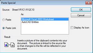
- In AUTOCAD, Paste → Paste Special
- In “Paste Special” Dialog Box, left side check the circle for “Paste Link” then as “Microsoft Office Excel Worksheet”
- Click “OK” BOOM!
the REX WAY
- Copy selection from desired program (ex. Excel)
- Go to AutoCAD
- Edit → Paste Special... Choose “Paste Link” radio button and choose Excel Spreadsheet
- To quote Peter: “VOILA.”
- Data changes AS you change data in Excel!
- Click on it and choose “Properties”
- Lock Aspect à NO and then put it on the ELEC-BLOCKS.dwg for whatever CCT it is
- Select “Print Quality” à Monochrome for CALC spreadsheets ONLY
AINT THAT THE ….
Yaroslav. Oh well, whatever lol
WORKS same with Generic Schedules too.
Revision Cloud (command “revcloud”)
- draw circle/rectangle around desired area
- select “Revision Clouds” then right click and cross hairs change to a pick box
- select circle/rectangle, right click to accept BOOYAH
- or just choose a thick line type
- or choose Arc Length Min + Max (3 times Min) and it be even!
Wipeout
- can select polyline to clear out area, BRING to FRONT/BACK as needed
- use any layer (except defpoints), then type command again “F” for frame to turn “OFF”
Random-ETC.
- For Federal Jobs, do not use make & model #’s “The specific overrides the General”
- “This is what I got from the Supplier, should I look into it further?”
- CTRL-A, de-select desired DWG and delete if can’t see anything that can’t delete
The Standard in Blocks: VLOCKS
- Use This File and start inserting objects
-
All at 1/8 scale, convert if need be.
Scott sez MAKE
YOUR OWN BLOCKS!!
1
. Select the objects you want to be blocks
from your projects, and scale them down to a base value using the scale from
the ACAD file you took the objects from. (ex. 1:100
scale it 1/100)
2
. Choose a common 0 degrees direction you
want all blocks to be aligned to.
3
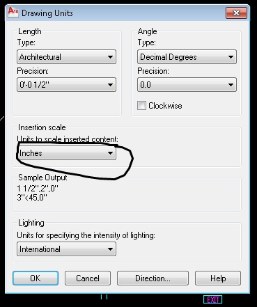
. In your cad file
where you be making your blocks, ensure that the proper drawing units are
selected (Format à
Units à Inches )
4
. Ensure all your objects that you want to be
blocks are on Layer 0.
5
. Ensure all your objects that you want to
be blocks are colour "By Block".
6
. Ensure all your objects that you want to
be blocks are linetype "By Block".
7
. Draw a line off to the side where you can
move your blocks to to create you block base points
(this makes it easy to snap to the line end point/block base point)
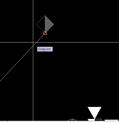
8
. Activate the Make Block command
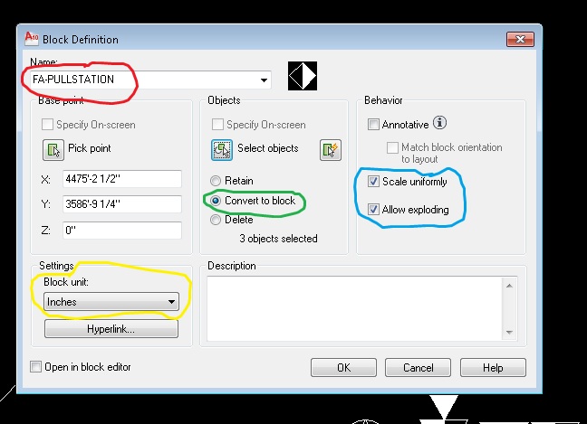
9
. Choose a name for your block, including a
prefix that will help identify and group your blocks, here are some examples:
1
. PWR - Power
2
. REC - Receptacle
3
. SWC - Switch
4
. FA - Fire Alarm
5
. COM - Communications (Telephone, data,
speakers ...)
6
. LGT - Lights
7
. LS - Life Safety (Exits, Emergency
lights...)
10. Pick
your block base point (snap to line end point).
11. Select the correct units (inches).
12. Select
"Convert to Block"
13. Select
objects (return to main screen and select all the objects that make up the
block), if you haven't done so before activating the Make Block command.
14. Select
"Scale Uniformly".
15. Select
"Allow Exploding" (unless this is an important item like an
engineering stamp).
Count Blocks Number with Quick Select à Block Reference à Name à Value and then view the Properties
Mass edit Blocks BLOCKREPLACE
● Manage Tab
● User Interface (CUI)
● Transfer Tab
● Customizations in New File → Open → Select Profile file
● Drag new Workspace to Workspaces under Customizations in Main File section
● Customize Tab
● Customizations in All Files section →Right click on new Workspace and select "Set Current"
● Press "OK"
● Top left-hand corner, adjacent to A icon there is a drop-down menu, click it and select "Show Menu bar"
● USE Color 53 as background color = EASY ON THE EYES
Abbreviations
URD – Underground Residential Distribution
URW – Utility Right of Way
Power service
· Primary feeder must leave the property at a 90° angle to the property line.
· EPCOR Requirements: Power feeders must be 10’ away from manholes, water lines, sanitation lines and storm lines and 7’ away from gas lines.
· Power feeders can cross above mentioned lines (not manholes) at angles close to 90°.
· Transformers (new type, dry-type or LNAN) must be 3’ away from windows & doors unless there is a blast wall separator.
· Transformers (old type, ONAN) must be 20’ away from windows & doors unless there is a blast wall separator.
· Transformers for Fortis requires 2 meter clearance.
· For selecting transformer sizes feeding residential units (houses/townhouses) EPCOR and Fortis use 2.5KVA to 3.0KVA per unit, however feeders and switches are sized according to the CEC.
· Fortis does not allow splitters (pedestals) between the transformer and residential meter. “Side boxes” (splitters mounted on the transformer) can be used to feed up to 16 secondary feeders.
- Fill in all the details on the FORTIS service website
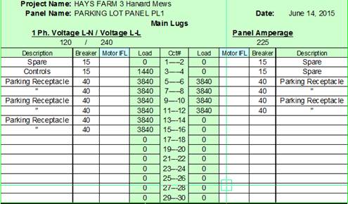
DETERMINE ACTUAL Service Request size...fully represent the loads of Main Switchboard Panel
- Take the various types, insert from Panels feeding in Main, using their Connected Values, find the current and act like 3 Pole
(see bottom of XLS, the "Main Switchboard Values")
- Demand Phase Current = ACTUAL current
- “rated” for Car Park Panel
- “connected” value from Panel A à e.g. Car Park
(de-rate @ Panel Switchboard)
![]() (Put this value in “Motor IFL” Panel Schedule in XLS)
(Put this value in “Motor IFL” Panel Schedule in XLS)
Telephone Service
· TELUS feeds from site entry to demarcation point (either a site pedestal or on wall mounted plywood in a meter/communication room).
· TELUS provides their own conduit for the contractor to install (Rigid Type DB2 PVC orange ducts).
· If the telephone service is longer than 100’ then pullbox(es) need to be installed for pulling of cables spaced at increment of 85’~90’.
· Telephone pedestals can feed a maximum of 12 units, up to 100m distance limit.
· Telephone cable must maintain a minimum clearance of 1.5m away from the transformer.
Cable television service
· SHAW feeds from site entry to demarcation point (either a site pedestal or on wall mounted plywood in a meter/communication room).
· SHAW provides their own conduit for the contractor to install.
· SHAW provides their own pedestals for the contractor to install (12”x12” plastic boxes 30” high).
· SHAW provides their own cable for the contractor to install.
· Cable TV conduits are 1 ½”C runs between pedestal and pedestal, and 1 ½”C run between pedestal and electrical room.
· If the cable TV service is longer than 100’ then pullbox(es) need to be installed for pulling of cables spaced at increment of 85’~90’.
· Telephone pedestals can feed a maximum of 8 units, up to 75m distance limit.
Service
Entry Request – Email
WE REQUEST
3 phase VLL/VLN for the voltages we so desire ALMOST
ALWAYS!
Hello Sir or Madam,
My name is ______________, and I work for _______________ as an electrical designer. I am working on a project called ___________ located at the following address:
[Legal address] [Municipal address]
I would like to request information on the location where the site electrical services can into this site, and information on the types of services available in this area. I have noted the following information on the type of proposed service that we are designing for this site:
[120/240V 1 phase] [120/208V 3 phase] [277/480V 3 phase] [347/600V 3 phase]
_______A
[Underground] [Overhead]
[Pad] [Pole] mount transformer [, is the option of pad-mounted metering available?]
Is this type of service available in this area? Are there any costs associated with providing this type of service, and if so, then what are they? If this is very costly, then what are the alternatives to this type of service?
I have attached a sketch of the site plan, which shows the proposed site entry location for the electrical service, the proposed location of the transformer, and the location of the electrical main distribution equipment. Please review this sketch and advise if there are any issues. Thank you very much for your assistance.
Service Entry Request – Map Sketch
Show the following information on the map sketch:
· North arrow
· Site address (legal or municipal)
· Site adjacent main streets and street names
· Proposed electrical service entry point, primary feeder run to transformer, transformer, secondary feeder run to main distribution equipment, main distribution equipment, and if the main distribution equipment is located within a building then the building outline and the electrical room outline
· Project name
· Our company name & contact information
 General
1 Foot Candle (FC) = 10 lux
IES - Illuminating Engineering Society
AFF - Above Fixed Floor
CFL - Compact Fluorescent Lamp
Types
Incandescent
- Colour rendition: Excellent
- Applications: Indoor/Outdoors
- No ballast required, dimmable
- Start-up: instant
Fluorescent
- Colour rendition: Excellent
- Applications: Indoor mainly, can be used Outdoors
- ballast required, need special ballast to be dimmable and for Outdoor cold weather
- Start-up: instant
High Intensity Discharge (HID) - Metal Halide (MH)
- Colour rendition: Good
- Applications: Indoor/Outdoors
- ballast required (noisy, long start up) need special ballast for faster start-up
- Start-up: 15-20 minutes for full brightness
HID - High Pressure Sodium (HPS)
- Colour rendition: Poor
- Applications: Outdoors mainly, can be used Indoor
- ballast required (noisy, long start up)
- Start-up: 15-20 minutes for bull brightness
HID - Mercury Vapor (MV)
- Colour rendition: Poor
- Applications: Not commonly used anymore, can be used Indoor/Outdoor
- ballast required (noisy, long start up)
- Start-up: 15-20 min for full brightness
Light Emitting Diode (LED)
- Colour rendition: Good
- Applications: Indoor/Outdoors
- Driver required (energy losses due to heat)
- Start-up: instant
General Type Info
“Low Bay” - Used for mounting heights less than 20’ above floor, ELSE “High Bay”
Specifying
DESCRIPTION – all the juicy details
SPECIFIED PRODUCTS
– generic brands, give client a few choices but not WHOLE model # “The specific
overrides the General”
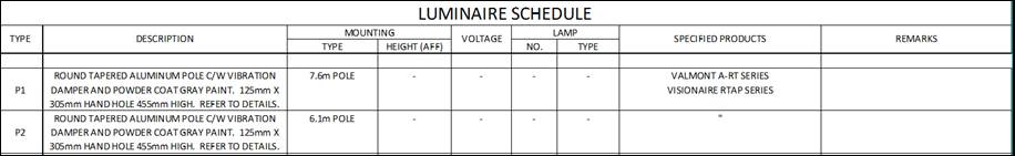
TYPE – Provide a word description of the type (e.g. Fluorescent 2 ‘by 4’ fixture or Fluorescent recessed 6”
round “pot” fixture)
Reflector – The metal reflector within the fixture to direct the light a certain direction (usually focused
downwards, sometimes wall-washers)
· Low iridescent – most common finish
· Parabolic – sends light down, good for computer rooms, reduces glare on monitors, but can produce a
cave effect where the ceilings and the top of walls are dark
· Specular – makes recessed “pot” lights appear to be off even though light is shining down
· In washrooms, mounted over stalls, do not specify reflectors that can act as mirrors
Lens –The clear material at the bottom of the fixture made of glass or plastic. It is common to not have a
lens. The lens can help scatter the light, and hide the lamp sources.
· Acrylic – common plastic material the lens is made of
· Pattern 12 – Indicates the thickness of the acrylic lens
· Prismatic – scatters the light and hides the lamps
MOUNTING
· Wall – mounted to the wall
· Recessed – mounted within the ceiling (indicate ceiling type, such as t-bar or drywall/gypsum board)
· Suspended – hanging from the ceiling (indicate distance suspended below ceiling), Chain (movable) or Cable (movable)
· Stem (Stationary). Choose a length that will be lower than structural joists, and if possible lower than
mechanical ductwork and piping. Write difference AFF’ + for exterior
· Surface – mounted to the underside of the ceiling (Don’t mix up with WALL)
Voltage
· 120, 277, 347V or Multi-tap (multiple voltage settings)
Ballast – Specify to match the lamp type (e.g. T8 ballast for a T8 lamp).
· Dimmable
· Cold weather start ballast – good for exterior fluorescent fixtures (down to -30°C).
Lamp – Note type/wattage and number of lamps per fixture
Additional features (Add to DESCRIPTION)
· Hazardous location – if located in hazardous location, the fixture shall meet or exceed the hazardous
classification, including being below the temperature rating of location.
· Damp location – Used in locations where moisture buildup can occur (e.g. showers, exterior under
roof overhangs).
· Wet location – Used in locations where direct water contact can occur (e.g. wash bays, exterior
exposed to rain).
· IP65 – fixture dust tight and prevents water entry from jets of water sprayed at it.
· IP66 – fixture dust tight and prevents water entry from powerful jets of water sprayed at it.
· Vandal resistant – Used in areas where there is access by the general public (e.g. main entrances).
· Lamp temperature colour (°K) – lower temp redder (warmer), higher temp bluer (colder), common to
specify 4300°K to 5000°K.
· Full Cut-off/Dark sky compliant – For exterior fixtures, eliminates most up-light (waste light)
components, required for LEED projects.
· IC – Insulated Ceiling rated for recessed installation in insulated ceilings. Non-IC rated fixtures cannot
be installed in insulated ceilings because the insulation leads to heat buildup that can cause fires, but
IC-rated fixtures are designed to dissipate the heat and not cause fires. Confirm with the architect
which ceilings are insulated (if any).
alt. labels L1, L2, etc.
F - Fluorescents
L - LED
MH - Metal Halide
HP - HPS
IN - Incandescent
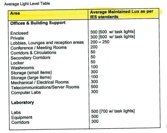
Illumination Levels (divide by 10 for fc)
T - diameter/12 → USE T8’s not T12 (40W)
T8 - general applications, 32W
T5HO - high up, gym, warehouse, 54W
T5 - 28W
TTT - triple twin tube
** USE T* or T5HO cuz T5 not much different from T8. use same types for maintenance purposes.
Minimum Light Levels – lux averages levels are determined by ABC (section 3.2.7 & table 9.34.2.7)
Egress routes 5 foot candles minimum at floor level
Service hallways 5 foot candles minimum at floor level
Storage rooms 5 foot candles minimum at floor level
Garages 5 foot candles minimum at floor level
Public water closet rooms 10 foot candle minimum at floor level
Recreation rooms 10 foot candle minimum at floor level
Service rooms 20 foot candle minimum at floor level
Laundry areas 20 foot candle minimum at floor level
Minimum Emergency Light Levels – lux averages levels are determined by ABC (section 3.2.7)
Egress routes 1 foot candle minimum at floor level
Calculation
Program Info
Reflectances
Ceiling: Offices-0.8 Industrial-0.5
Wall: Offices-0.5 Industrial-0.3
Floor: Offices-0.2 Industrial-0.1
Suspension length – distance from bottom of ceiling to bottom of light fixture
Work Plane height – usually either floor level (0’ AFF) or desk level (2 ½’ AFF)
Each head → Add W
Note Vdrop 5% to know where to put battery pack.
![]() Battery → warm area - for remotes, panel
Battery → warm area - for remotes, panel
General Lighting Notes
Controls
· PEC → Photo Electric Cell turns on or off the lights depending on the ambient light levels (can be
adjusted)
· TC → Time Clock turns on or off the lights depending on the time of day (can be adjusted)
· HOA → Hands Off Automatic switch (On, off, auto) which is a switch allow changing between
manual on, manual off, and automatic on/off. The automatic portion is controlled by relays receiving
input from other devices (e.g. PEC, TC). HOA’s can be used to control other types of equipment other
than only lighting (e.g. motor control)
· LV → Low Voltage switching which can combine the above mentioned controls by the means of using
line voltage relays to switch on and off the lighting circuits (like a normal manual line voltage switch)
which is controlled by a programmable controller which can receive inputs from multiple low voltage
switches, PEC’s & TC’s, as well as specialty switches such as motion sensors.
Wiring
· Run rigid conduit running from junction box to junction box and flexible conduit running from
junction box to light fixture (not more than 6’ of flexible conduit)
Consumption Levels
· Maximum consumption levels are determined by the Model National Energy Code (Part 4), IESNA,
ABC table 9.34.2.7 and LEED.
Circuiting
· For fixtures with ballasts, add a factor of 20~25% of the lamp wattage to account for the ballast
wattage and inrush current for the ballast. Ballasts lose energy in the transfer process converting the
voltage and frequency for the operation of the lamps. Ballast energy loses are usually in the form of
heat and noise.
Installation Considerations
· In meeting/boardrooms where a ceiling mounted projector will be used, ensure that if suspended light
fixtures are used, that they are not located between the projector and the screen blocking the projector.
· In washrooms, ensure that if recessed linear light fixtures are used, that they do not have mirror-like
reflectors allowing occupants to use as mirrors to look into occupied stalls.
· For showers, confirm with the architect the type of shower (either open to the ceiling like in recreation centre change rooms or packaged units that include the shower ceiling - like a tub flipped on its side). After this has been confirmed
then the appropriate lighting can be chosen for above the shower. For installation in a packaged
shower unit, choose either no lighting or a small low voltage (120V or less) recessed pot light damp
location rated with a small radius (6 inches or less).
- Lighting Large Equipment → 347/600 OK
- LV relays use relay panel (consult E:\Guides\Lighting\Controls)
- BALLASTS take wattage. Rule of thumb based on Lamp Wattage: add 25% to compensate
(converts frequency & voltage for lamp use. not perfect, creates waste heat & sound. ie. extra energy) SOURCE: Ron Krewulak office@rakeng.com
Fluorescents, HIDs and LEDs
== LAMP == e.g. T8 4RT → 32W
- When ESTIMATING check catalog
2’ = 14 W @ T5
4’ = 54 W (not HD = 28W)
3’ = 20 W
- hand drawing T-BAR
- centre lights, draw around it.
- Lighting different heights - more lamps? specify suspended “blah blah” height
- Light that shines on ceiling too (too low, ceiling = dark, get cave lighting effect)
- Coordinate lights with diffuser locations
- Use 1-1P-15A switch is required for each 15A circuit. 2 pole switches are used to control 2 circuits. 20A switches to be used for 20A circuits. Fluorescent lighting can be 2-level switches, 3 way, 4 way switching to be associated with 3 way 4 way switch. Switches to be located a min. of 36” from bathtubs.
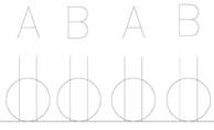
- SPACING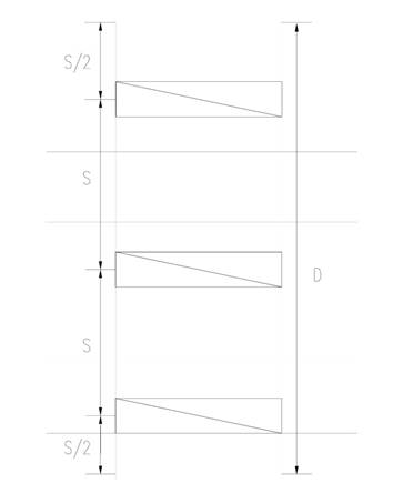
D = distance
S = spacing
# of fixtures
USE S value closer to width of distance of T-Bar
EXAMPLES
Condo/Apartment Suites
- “nook” lights should be no more than 4 ft from the wall and shoot have a “+36” labeled dedicated circuit near the switch for the light
Warehouse/CRU/Retail
- Light level should be approx. 4 W/sq ft (80-100 fc) continuous rows 2 lamp strips 8’ o.c. or 2’x4’ lamp fixtures on 8’x10’ grid or 400 W MH fixtures complete with diffused coated lamps and lens on 12’x12’ grid
Residential
Washrooms
- Light switch is generally placed closer to the door than the fan switch - BOTH must be at least 3’ away from shower/bath tub (unless GF protected)
- Wall mounted fixtures are normally placed over sink. Extra ceiling lighting is included if there is a divider or something that would cut down on the amount of light in an area such as a tub
Offices
- Line up lights with ceiling grid, avoiding crossing T-BARS
- separate offices need light switch
- Light level should be approx. 4 W/sq. ft (80-100 fc) Open office areas 2’x4’ 4 lamp fixtures on an 8’x8’ grid, 10’x10’ office 2 - 2’x4’ 4 lamp fixtures or 3 - 1’x4’ 2 lamp fixtures, 10’x15’ office 3 - 2’x4’ 4 lamp fixtures or 5 1’x4’ 2 lamp fixtures
- Board Room Light level should be approximately 3 W/sq ft. (40 - 60 fc) Use 2’x4’ 4 lamp fixtures over boardroom table and pots or wall washers around perimeter of room. Do not locate pots over seating area. Luminous ceiling, egg-crate lens and valance lighting could be used. Provide good whiteboard/chalkboard lighting.
- Reception Area Light Level should be approx. 3W/sq ft (60 - 80 fc) use 2’x4’ lamp fixtures on an 8’x6’ grid. For lights 6’ o.c. sunshine ceiling over reception desk, (2 lamp strips 9” - 12” o.c.) complete with egg-crate lens, track lighting, wall washers, sconces, or any combination may be used.
- TRACK LIGHTING, SPLIT 4 FOOT SECTIONS FOR EASY CIRCUITING AND SWITCHING
Electrical/Mechanical/Storage Room
- Light level should be approx. 2W/sq ft (50 fc) Use 2 lamp 4’ strip lights 8’ o.c. surface mounted or chain suspended.
Kitchens
Hallways / Corridors
- Wall mounted light fixtures mounted on alternating walls about every 12 feet
- Use wall sconce on 12’ centres (max) Try to locate as close as possible to suite doors. Valance or cove lighting may also be used.
- Determine type of ceiling used from ARCHITECT. These can be suspended acoustic tile (T-bar), drywall, linear metal, sloped, exposed joists, pre-cast concrete, etc.
- where ceiling is fire rated fixture to be boxed in to maintain fire rating.
- Schools, government buildings and “good” quality projects (LOL) can have 2’x4’ 3 lamp fixtures, coffered ceilings, 5’x5’ grids, indirect lighting, air handling fixtures, etc.
- Max 6” depth is required to recess fixtures. 24’ of track is equal to 1-15A circuit 24” of track is equal to 1 outlet. Specify 1500W slide type dimmers complete with radio noise depressant. Max dimmer load is 1200W even for 1500W dimmer
- heat lamps in washroom require 0-15 min spring loaded timer
- pool lighting to be located over deck and side, not over the pool or in pool walls
Stairwells
- Provide lighting, emergency lighting and on receptacle at each landing
Elevators
- disconnect switches for every elevator (one for the elevator motor, one for elevator lights)
- Elevator pits:
light switch mounted adjacent to sliding door and 4 ft strip light with wireguard
Building Exteriors
- Put lights at entrances and loading bays only, unless otherwise specified, PEC/TC (photo elect. cell / Time Clock)
Parkades
- 8 ft. strip lights generally go every third parking space (about 27 ft off center)
Attics
- Keyless porcelain lamp holders complete with a 100 W incandescent light spaced along walkway approx. every 25 ft controlled by switch c/w pilot light
- wall mounted lamp holders (WP if located exterior) controlled by switch complete with pilot light (mounted in the interior)
Site
RULE OF THUMB
Pole height - double distance between FOR EVEN DISTRIBUTION
LUXICON/DiaLUX Guide
WIZARD
1. Define Room
- base values from IES Levels Table
- add ceiling grid
2. Select... insert IES if possible
3. Calculate Layout
- WHAT fc used
- ROTATE 90 where need be
4. Check export point by point and make report, etc.
Light Pattern:
- even distribution circles go through more lights
- more circular pattern
- less rings around fixture pattern
- consider cost
NEW PROJECT
Procedure:
- Setup Geometry
- Insert fixtures (find, right click → insert NOT open, manually add dimension if can’t insert/OLD IES
RIGHT CLICK FIXTURE *** Split to delete & move fixtures
OR File → Import .. Luminaire files
- Insert Array (![]() button)
button)
- Calculate (![]() button)
button)
- Go through tabs to adjust and add where needed
- Colour Tree for fun or massive details
- insert OBJECT Z:”ORIGIN” → ½ Height:H
- right click on ROOM … “Edit Room Geometry”
* p.25 Tutorial “Room Elements” → click ‘Plan View’
- ![]() GRID button can do T-Bar
GRID button can do T-Bar
- CHANGE geometry - point by point INSERT
- EXTERIOR - set origin by right click “SET DWG or DXF origin here” coordinates distance etc.
- INSERT OBJECTS to recreate building sections
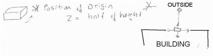
- to hand insert L shaped geometry, etc.
Project Tab, right click “Room” name, edit geometry
“Room Editor” can insert coordinates
OR used “Edit” menu
1. Setup the place, basic working area imported CAD etc
2. Insert Calculation Grid to be size of area
3. Choose Fixture
4. Insert Field Arrangement
5. Adjust FC / Rows of fixtures as needed.
6. Do Calculation to check isolines
7. Adjust Where Necessary
8. Print and Enjoy
- General put on 120/208V
- use 1A/receptacle: 15A cct = 12 recept (considering 80%) 1.5 A / receptacle
- RULE OF THUMB, practice 8/cct P = VI = (120)(1.5) = 180W
- specific appliance / computer / kitchen = 1 or 2
DEDICATED max it out to 1440 / cct even if there’s 1 or 2 (add “variety” put on different circuit in a room)
- On equipment spec. with Amps Given then use 1.25 to find breaker size
Basic LAYOUT TIPS
1. ADD Total usable wall space
2. ROUND UP = # of Total receptacles ![]() MIND
THE CEC
MIND
THE CEC ![]()
- Step Down Transformer for panels
- 0.5 HP or less → 120V else max voltage 3 ph
- GO FOR...small current, large voltage GIVEN constant motor spec.
- CEC 8-400 - Automobile heater receptacles
- Heating vs Cooling → use bigger else ZERO “not run @ same time”
FACTORS that INCREASE WIRE SIZE
- temp based on table 5A
- # of phase wires in conduit, magnetic fields (table 5C)
- voltage drop due to resistance of length (table 3) see “non motor loads, min protection size” Southwire Guide Conductor Info Chap 3.5 XLPE
- TEK cable use XL ex. 4#1 XL TEK
EXAMPLES
Condo/Apartment Suites
- Receptacles: for dwelling units, at most 6 feet from the end of the wall (eg. USABLE Wall Space door or closet) ELSE max. spacing of 12 ft between receptacles
- try to get receptacles as far away from the end of the wall and other receptacles without exceeding the max distances. Position receptacles for easy access
- any space in between doors/closet in a bedroom that is 3’ or more shall have a receptacle
- All “GF” (Ground Fault) recept. on a circuit only need the first recept on the run to have “GF” protection. The rest will be covered (protected) by the first
- Receptacle near bed “AF”
- Sauna/Tub in room - within 3 m → 9 ft 10” radius need to be GF protected
- Condensing units go together with fan coils
- Panels are generally placed in the least visible area, such as a storage room or mechanical room
- Telephone symbols are placed in bedrooms where the head of a bed is more likely to go
- Television and telephone symbols go on roughly the opposite side of the room
Warehouse/CRU/Retail
Residential
Hallways / Corridors
- Receptacles spaced about every 30 feet (10 meters max; all on one side)
Washrooms
- GF Receptacle within 1 meter of sink
Kitchens
- Microwaves and fridges require dedicated receptacles
- Microwaves generally go between fridge and stove, Order is Fridge, Micro, Split....
- Other receptacles are to be split. Split Recept. are to be placed along the counter spaces greater than 1 ft in length (not including areas that are directly behind a sink) and are to be placed such that no point along the counter is more than 35” from a split receptacle.
- Circuit them alternately on the panel connections. Avoid placing split receptacles in inconvenient locations on corners
** Refer to CEC 2009 26-712 (d)(iv) 15A split or 20A
- Put a phone line in the kitchen if possible on the counter furthest from fridge
Laundry Room
- Laundry 15 A – 1 P dedicated
- DRYER – 30A – 2P special receptacle due to heating element
Elevators
- Elevator machine rooms
- disconnect switches for every elevator (one for the elevator motor, one for elevator lights)
one motor for every elevator
exhaust fan
dedicated receptacle and telephone outlet
- Elevator pits:
telephone outlet on opposite wall from the sliding doors
dedicated receptacle mounted adjacent to sliding door
Offices
- 2 recept. 1 telephone jack, 1 data, per computer desk
- 10 meters max. between recept along hallways. That measurement continues through doors and around the corners of walls. There is no set rule for the distance that they should be from a door. Convenience is a deciding factor.
- Fax machines need telephone connection and a regular duplex receptacle
- Photocopiers need a data connection and dedicated receptacle
- Each desk with computer should have data, telephone and 2 duplex receptacles
Building Exteriors
- Weatherproof receptacles every 120 ft
- Receptacles are not required outside of office buildings but one (WP) is usually placed outside the main entrance (Refer CEC 702 “while in use”)
- Receptacles for car parking spaces to be mounted on a post positioned 3 ft back from the curb to prevent idiot drivers.
Parkades
- Receptacles spaced on alternate sides approx. every 55 ft
- ADD typical detail of Car Park Controller – like a relay.
Attics
- Receptacles spaced along walkways located along the side of the plank walkway every 30-40 ft
- Receptacle (WP if located exterior)
- Roof: place receptacle for MAU
GENERIC Communications (Telephone / Data) Checklist
- Video Conferencing?
- CCTV (Close Caption TV for security)
- Wireless or hardwire data
- Security
- Nurse Call
- Public Address
- Door answering
- Sound masking
- Clocks (Timer)
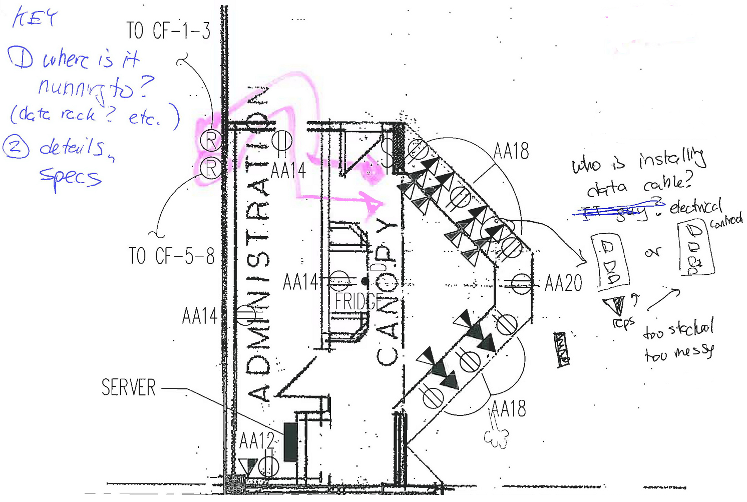
![]() Data Rooms provide 19mm THICK plywood backboard
around room’s walls (use generic KEY NOTE)
Data Rooms provide 19mm THICK plywood backboard
around room’s walls (use generic KEY NOTE)
![]() Receptacles “SS” for Surge Suppression on Cable
TV, Data, Telephone
Receptacles “SS” for Surge Suppression on Cable
TV, Data, Telephone
SECURITY
DOORS
Crucial in fire protection and preventing people from entering illegally. See ABC – Security 3.4.6.15
Magnetic Door Locks
Security
Magnetic Locks – prevents unauthorized access - are required to release upon
the 2nd stage fire alarm.
Magnetic lock
Magnetic Door Hold Opens
Magnetic
Door hold opens are connected to the fire alarm system and are required to
release upon an associated active smoke detector or from the general alarm via
ABC 2.1.8.12
Magnetic door hold open device
Door Closer
- Keeps door back in CLOSE position
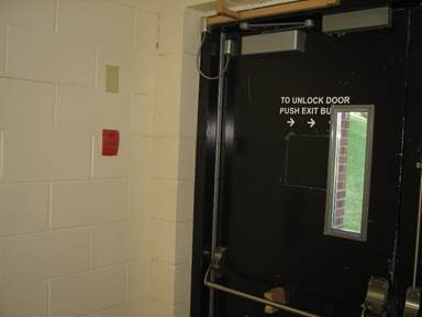
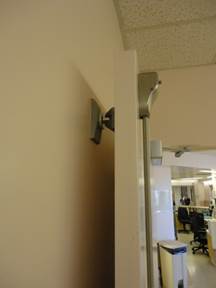
REX aka Request to Access
- Press button to leave.
VS REGULAR Door STRIKE
Requires card / Fob key access. Does not act as any real fire suppression/fire door. Like front door.
When FA reset, doors don’t auto reset.
Enclosure Ratings
Ingress Protection (IP) ratings are developed by the Euros or NEMA environment rating 1 to 12
- For use with panel protection in wet locations, submersibles (special receptacle/disconnects)
REMEMBER!!
Mechanical Equipment
(Incorporating into)
- Force flow will be at all entries unless it is not a work door.
- Provide ceiling fans when required (high ceilings) if mechanical does not
- RTU zoning system: wiring for thermostat and damper to RTU panel. Install S/A bypass.
- Ensure all electrical have exhaust air if transformers are installed.
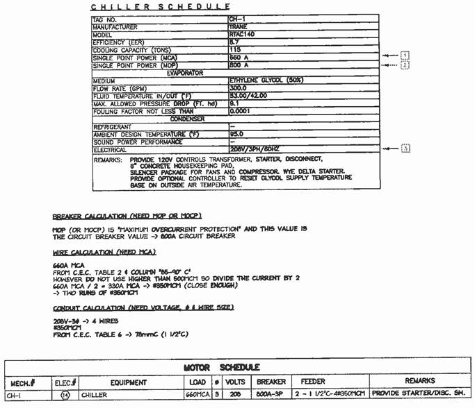
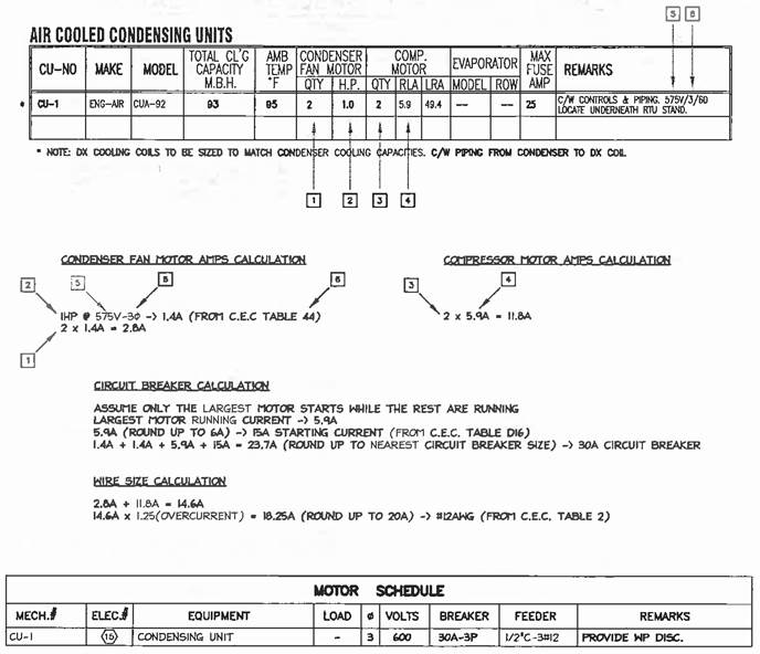
- Include Wire Size and all important details in Motor Schedule. Refer to Common Motor Wire Sizes by Howie Patrick.
- sometimes the conductors that are connecting to the junction of the motor, sometimes there's temperature implications there." 28-104 (2)
Replace mechanical block symbols with the following electrical symbols in the appropriate locations:
![]()
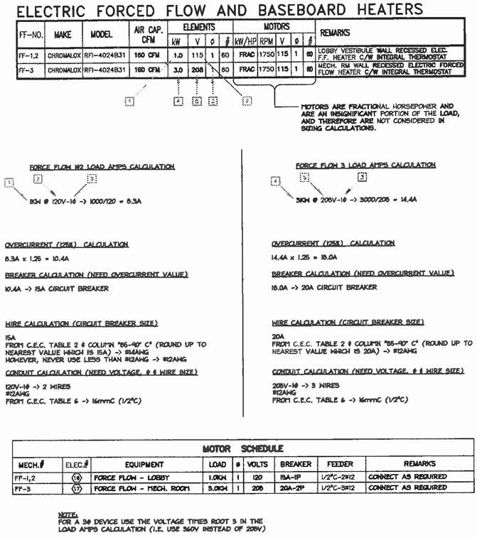
- FF: Force Flow heaters (Connect as required)
- BB: Baseboard heaters (Connect as required)
- RH: Range hood Fan (Connect as required)
- B: Boiler (Provide Switch)
- MD: Motorized Damper (Connect and interlock to CO/NO & EF as indicated)
- CO/NO: CO/NO detector (Provide 120V connection, interlock with motorized damper and EF)

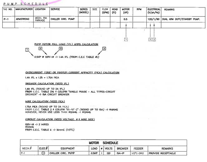
- P: Pump (3ph or 1ph/240V: Provide started & disconnect switch or Prodide Receptacle)
- F: Furnace (Provide switch)
- EF: Exhaust Fan (Provide switch)
- CF: Ceiling Fan (Provide variable speed switch)
- UH: Unit heater (Provide switch)
- MU: Make-up air unit (Provide starter & disconnect switch)
- CU: Condensing unit (Provide disconnect switch)
- FC: Fan coil (Provide switch)
- RTU: Roof top unit (Provide WP disconnect switch)
- Elevator (Provide 2 disconnect switch: one each for motor, lights)
- SF: Supply fan - Disconnect/Interlock with lights and ________

- HWT: Hot water tank (Provide receptacle)
- WH: Water heaters (Provide receptacle)
- IF: Infrared heaters (Provide receptacle)
Equipment Sizing
Examples
![]() see NAIT notes.
template used for APARTMENT BUILDINGS
see NAIT notes.
template used for APARTMENT BUILDINGS ![]()
Refer to ABC 1997 Edition, CEC 2006 Edition
1. DETERMINE Occupancy classification (ex. for apartment building is Group C from ABC Section a-3.12.1 1) page 424)
2. Occupancy Load determined by ABC Section 3.1.16.1 1) b) (page 62) and the number of sleeping rooms in the building (eg. 2 persons x # of sleeping rooms = Occupant Load)
3. Determination of the fire alarm system requirements by A.B.C. Sections 3.2.4.1 (page 93) 1) 2) c) and j) and apartment building information, number of stories, total occupant load, and if building is sprinklered.
4. Professional Engineer required involvement by ABC Sections 2.3.3.3 1) and 2.3.3 1 2) c) (pages 20, 19) Involvement of P.Eng. is required if building is one storey and greater than 400 m2 or two stories and greater than 200 m2, or three stories and greater than 133 m2 or four or more stories.
5. Either 1 or 2 Stage system can be used. Determined from ABC Section 3.2.4.3 1) d) (page 93)
6. Signal in Fire Department requirement determined from ABC Section 3.2.4.7 2) and 3) (Page 94) and whether the building is sprinklered or a 2 stage system. If a signal is not sent to the Fire Department then Section 6) (page 94) now applies stating that a notice shall be fixed to the wall, beside every pull station, stating the Fire Department shall be notified in the event of a fire emergency, including the telephone number to contact the Fire Department.
7. The required number of zones is determined by the ABC Section 3.2.4.8 2) (pages 94,95) with the following information from the building; the number of stories, the area of each storey, the number of shafts requiring smoke detectors (e.g. Stair or elevator) air handling system requiring duct smoke detectors (and number of zones for the air handling system) and sprinkler system (and number of zones for the sprinkler system).
8. An annunciator is determined to be required by ABC Section 2.2.4.8 3) (page 95) if there is more than one zone in the building (determined above) The required positioning of the fire alarm annunciator (usually part of the Fire Alarm Control Panel, FACP for short) is determined by the ABC Section 3.2.4.8 1) (page 94)
9. Fire Detector locations are determined by ABC Section 3.2.410 (page 95) and from the information from the building regarding what each room is used for. Unless otherwise directed use fixed temperatures (197 F) heat detector for boiler/mechanical rooms and use fixed temperature (135 F) or rate of rise heat detectors for all other required heat detector locations.
10. Smoke detectors (SD) locations are determined by ABC Section 3.2.4.11 1) d) for corridors and e) for stairwells (page 96) using the following procedure:
- Corridors
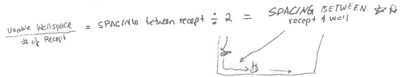
- Determine corridor length and width. Using the Table below and corridor width, determine the maximum distances (between SD and SD and between SD and end-wall of corridor). To determine the number of SD’s required use the length of the corridor and divide by the maximum distance between SD and SD (first column) and round up to the nearest integer.
e.g. ![]()
Then to determine actual spacing of SDs take the length of the corridor and divide the number of SDs (spacing between SD and SD). Then take half this value to find the spacing between SD and end-wall.
e.g. ![]()
e.g. ![]()
|
Corridor Width |
Max Distance between SD & SD |
Max Distance between SD & end-wall* |
|
C.W. ’ ≤ 1.5 m/4.9’ |
18.0m / 59’ |
9.0m/29.5’ |
|
1.5m/4.9’ < CW ’≤ 3.0m/9.8’ |
16.5m / 54’ |
8.25m/27’ |
|
3.0m/9.8’ < CW |
13.0m / 43’ |
6.25m/21.5’ |
* If the “end-wall” is a fire wall with a magnetic door (hold open device for the doors which de-energize during a fire to automatically close the doors and complete the fire separation wall) then a SD must be located within 1.5 m (4.9’) from the fire door on both sides of the fire wall. This is in accordance to Alberta FA Systems Installation, Testing and Maintenance Revised 1994 Appendix D NFPA 80 Detector Installation Guide for Door opening protection.
- Stairwells
- Determine the number of stories, locating the first SD at the top of the stair shaft and if the building is 5 stories and greater, THEN an additional SD is required every 3 stories below the previous SD
e.g. 3 storey building: 1 SD on the 3rd storey
5 storey building: 1 SD on the 5th storey, 1 SD on the 2nd storey
- Open Areas
- Each SD can protect an area up to 81 m2 (870 ft2) according to ULC S524
11. Duct smoke detectors (DSD) are determined by ABC Section 3.2.4.12 (page 96). Depending on size of the building, the air handling system may need to be broken into zones monitored by DSDs for larger buildings. If this is not the case, the system should have one DSD located a min. of “6 duct widths” in length downstream from the air inlet/supply fan.
12. Pull Station locations are determined by ABC Section 3.2.4.17 (page 96) [3.2.4.15 page 3-77]. One near every exit from a floor, on the side of the door without the hinge, facing in toward the center of the building. Not placed inside of a vestibule or stair shaft, but rather interior to the building near doors exiting through these areas.
13. Horn or Bell and Piezo (Buzzer) locations are determined by ABC Sections 3.2.4.18 and 3.2.4.19 (pages 96. 97). Horns (or Bells) should be located in corridors, common areas, and anywhere else such tht the audible signal can be heard in other rooms (e.g. storage, janitor, electrical, mechanical rooms). Spacing is determined by the dB rating of the device, with consideration that doubling the distance between devices reduces the dB rating by 6, and the ABC states that the dB shall not drop below 75dB and shall be 10 dB above the ambient noise level of the room. Piezos should be located in individual suites so that the signal may be heard at 75 dB in the sleeping room with the doors closed (normally located within each sleeping room).
14. Strobes (visual signals) locations are determined by ABC Section 3.2.4.20 (page 97). Especially 3) which states wherever horns/bells/piezos are located there must be a visual signal device within that region. Normally this is accomplished by using horn/strobe or bell/strobe combination units and a strobe device mounted directly 2’ above piezos.
15. Smoke Alarm (not part of the Fire Alarm System) locations are determined by ABC Sections 3.24.21 (pages 97, 98) and 9.10.18 (page 272). Smoke alarms should be located within close proximity to sleeping rooms (5 m) but not directly in front of the door to the bathroom to prevent false alarms due to steam from showers. Also they must be located within 15m from every other point in the unit.
16. Sprinkler flow switches and supervisory devices shall be in accordance to ABC Sections 3.2.4.9 and 3.2.4.16 (pages 95, 96)
17. Fire pumps for sprinkler systems shall be installed in accordance to ABC Section 3.2.5.19 (page 103). This device is only required when the water supply is unable to provide the necessary water pressure for sprinklers, hose systems and stand pipes, and is usually only necessary for buildings located outside of city limits.
18. Emergency lights location and power is determined by ABC Sections 3.2.7.3 and 3.2.7.4 1) a) and b) iii) (page 106) and also by CEC Section 46-106, 46-210, 46-306. A minimum of 1 foot candle must be maintained along all means of egress from a building during emergency situations where the building loses power.
19. Exit sign locations and power is determined by CEC Section 46-400. Exit signs indicating means of egress must be visible from every point along the means of egress.
EXAMPLES
![]() Emergency
Lighting and exit lights are required in all public buildings. Battery pack
mounted at 7”-6” AFF and connected to lighting circuit. Exit lights to be
located directly over door and provided with a dedicated 15 A circuit (SEPARATE
BREAKER) Max. 4-6 remote heads per battery pack. Exit lights to be provided
such that two means of egress are visible from any point.
Emergency
Lighting and exit lights are required in all public buildings. Battery pack
mounted at 7”-6” AFF and connected to lighting circuit. Exit lights to be
located directly over door and provided with a dedicated 15 A circuit (SEPARATE
BREAKER) Max. 4-6 remote heads per battery pack. Exit lights to be provided
such that two means of egress are visible from any point.
Condo/Apartment Suites
- Each bedroom needs a fire alarm piezo/strobe unit next to the light switch to meet 75db criteria and a smoke alarm outside of the door
- Each bedroom that is not directly next to another may require its own smoke alarm just outside the door. Smoke alarms shall be placed on the same circuit (refer to Fire Alarm Guideline)
Hallways / Corridors
- Each person should be able to see an emergency exit sign and emergency lighting from their entrance door. Ideally, they should see 2 exit signs
- Emergency lighting spaced about every 45 feet
- Fire alarm horn/strobe units spaced about every 50 feet (for bell/strobes every 70 feet - refer to Fire Alarm Guideline)
- If halls are exposed to elements (outdoors) the emergency lighting, pull station, horn/strobes. etc/ need to be labeled “WP” weatherproof
- levels should be approximately 3W/sq ft. (25 - 30 fc). Use 2’x4’ 4 lamp fixtures 12’ o.c. mounted perpendicular to corridor or 1’x4’ 2 lamp fixtures 8’ o.c. mounted perpendicular to corridor. Use recessed pots 6’ o.c. wall sconces at 12’ o.c.
Stairwells
- Provide lighting, emergency lighting and on receptacle at each landing
- Stairwell entrances should be marked by exit lights and there should be a fire alarm pullstation and horn-strobe outside of them
- should have smoke detectors at the top. The Code says that every 3rd floor beneath that needs one too (refer to Fire Alarm Guideline)
Elevators
- a smoke detector on top of every elevator shaft
- Elevator lobbies need smoke detectors and emergency lighting/battery pack combo
- Elevator machine rooms
- disconnect switches for every elevator (one for the elevator motor, one for elevator lights)
fire alarm smoke detector
Offices
- Fire alarm pull stations are only needed near areas where you can leave that floor. i.e. stairwells
- Tall buildings usually have an emergency generator that will kick in to supply power to emergency lighting, so battery packs not required
Parkades
- Emergency lighting only shines approx 30 ft radius
- Fire Alarm pull stations are only needed near areas where you can leave that floor (i.e. stairwells, main entrances, exit)
- Fire alarm horn/strobes spaced every 100 ft
- CO detectors spaced every 100 ft
Attics
- Bell/horn/strobe (WP if located exterior)
- heat detectors spaced approx every 30 ft.
- Duct smoke detector mounted in MUA duct
Doing Schedules:
Fire Alarm (DCL) Device Point List I-000 = Smokie, Thermal/Heat Detector Pull Station, Control Module, Monitoring Module, Duct Smokie, EOL
Notification Appliance Circuit (NAC) Device Point List N-000 = Bell, Strobe or Horn & They Combo
RR = Rate of Rise
M – Manual Station
MM – Monitor Module
HT – Fixed Temp. Heat
PE – Photo Electro. Smoke
CM – Control Module
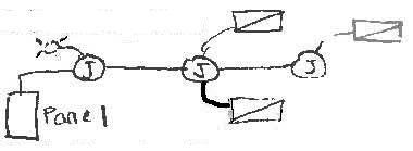
Voltage Drop Analysis for Fire Alarm Devices
1) Draw wire connections from device to device as if you were wiring them
2) Measure the length between each device
3) Estimate the wattage per device starting from the end point. i.e. each head = 12.5W, exit sign = 4W
4) As you go from each device, add the wattage up.
5) Use the attached chart in The FA Voltage Drop Guide to determine wire size.
6) #6 and higher is BAD DESIGN!
FAVI Notes and
Tidbits:
HOW TO DO A VI
ü Make sure fire alarm panel breaker red, locked
ü Note Fire Alarm Panel Model
ü Get the names of all involved: Electrician. Fire Alarm Tech
ü Record TROUBLE (aka “Open” wire in circuit, note if missing) – Alarm/Supervisory Trouble (indicated on Panel) – Ground and corresponding circuit Address
ü Test Heat, Smokies, Pull Stations (DCL, Initiating Devices)
ü Along the way, test Isolation Modules (verify which zone it knocks out) AND EOL Resistors - for Open and Ground
ü Test Strobe are operational (NAC Notification Appliance Circuit, Open, Ground circuit)
ü Various specialized people to meet: Elevator (Go Up Shaft & test Smokie), Kitchen Suppression, Sprinkler:
- Flow Switch 30-45 Seconds [100 seconds OK by Kirk] to Alarm, Test - cover off to set off Tamper
ü Do a LOAD TEST
o Arrange with Electrician and FA Guy to turn off the power to FAP for 12+ hours overnight.
o Get battery readings (V, A) at all batteries (FAP, booster panels) before and after
o Test early in morning best. 30 minutes RING THE BELLS and verify all strobes working. Silence piezos where necessary.
Some TIDBITS
Refer CAN ULC S524 on installation / ULC Table C5
Sound meter: Audible 65 dB - +10 dB for Ambient
Manometer - Duct Test Airflow, Is there DUCT LED Indicator
Ancillary Systems – HVAC, Control, Elevators, Kitchen Suppression System
Conventional Non addressable with a Monitor Module, used for devices that are explosion proof, hard to reach areas, etc.
Measure from centre of floor:
Horn Strobe: 1.8 – 2m
Pull station: 1.1m
Make sure: “the fire alarm panel was fed from the existing panel board, however, this does not comply with CEC rule 32-108 (refer to the handbook) for a better explanation than the Code. The intent was for the fire alarm panel to be fed from emergency power from the terminals of the transfer switch. This will need to be corrected.”
Q: How do you send monitoring signals
from a building to your Signals Receiving Centre?
A: A communication link between a monitored premises and the FMC SRC (Signals
Receiving Centre) can consist of either an “Active” or “Passive” connection
and/or some combination of both methods.
An Active connection means that the communication link is monitored on a continual basis, 24 hours a day, 7 days a week, 365 days a year. If communication between the monitored premises and the FMC SRC is interrupted for any reason, the FMC SRC is notified within seconds of the interruption and the FMC operator can take immediate action.
A Passive connection consists of a communication link that is not monitored on a continual basis. When a fire alarm monitoring panel using a passive connection has data to send, it will establish a link with the SRC, transmit it’s data and then disconnect. Passive connections are programmed to send a test signal into the SRC only once every 24 hours, and in the event an interruption in communication occurs, it can take 24 hours or longer for the SRC to be notified. When monitoring over a “Passive” connection, CAN/ULC-S561 requires that 2 non-redundant forms of communication are used. Current methods of communication for this method include Analog Phone (POTS) lines, Cellular, and Internet (IP).
6. PANEL LOAD SIZING/SCHEDULES
Panel Sizing
- Draw Telephone Board 4ft (small shop) 8 ft (apartment building)
- Draw Panel as per specs
- The panel amperage size is based on the load (kW) that is connected to the panel. For every circuit breaker determine the load either by equipment rating (e.g. a load from mechanical schedule may specify kW rating) or calculate the load from the circuit breaker amperage rating multiplied by the voltage and the 80% continuous load rating (e.g. a 15A-2P breaker → 15A x 240V x 0.8 = 2.9 kW) Loads need to be divided into 6 categories and de-rated using the factors listed below. The six categories are:
Lighting 100%
Receptacles 50%
Heating 75%
Mechanical 100%
Humidifiers 50%
Furnaces 75%
- Note: 1-120V = single phase; 1-208, two phase 3-208, 3 phase
- DETERMINE how much BREAKER LOADS can be on one circuit breaker!! then fill up the panel
Breaker Size x 80% x voltage = LOAD
15A x 0.8 x 120V = 1440 W max per cct
20A x 0.8 x 120V = 1920 W / cct
2-pole loads (15A - 2P)
15A x 0.8 x Vline to line
15A x 0.8 x 208V = 2496 W
EXAMPLE LIGHTING LOADS
Fluorescent 2 x 32W T8 20 @ 120V
(15A-1P)
2 x 32 x BALLAST FACTOR (+25%) → room for upgrade
2 x 32 x 1.25 = 80 W = 1600 W
THUS MAX Wattage / each fixture = 1444W / 80 = 18 fixtures / breaker
ex.
TYPE - # Lamps x W x BALLAST = TOTAL W x # of fixtures = TOTAL LOAD
A - 3 x 28W x 1.25 = 105W x 8 = 840
B - 2 x 28W x 1.25 = 70W x 4= 280
C - 2 x 32W x 1.25 = 80W x 4 = 320
D - 1 x 54W x 1.25 = 67.5W x 3 = 202.5
Add it all up = 1642.5 W → JUST enough for 1P-20A
NOTE:
Voltage Increases → Smaller Breaker
Power CONSTANT → Current Decreases
- Once all loads are converted into kW and de-rated, sum up all loads and using the voltage find the Amperage
[e.g. single phase → 62kW/240V or three phase → 72kW / (√3 x 208V) ]
- The panel will need to be at least rated for the determined amperage (e.g 400A rating for 258.3 A or 200A rating for 200A)
BASICS
- have physical space? can take that size?
- Howie - balance panel large loads @ bottom
- Nameplate info of panel. look up on site. MIGHT HAVE SPACE but not capacity. BALANCE while circuiting
- BALANCE on circuit panel 3 pole A-B-C neutral NOT!! B-C-A etc.
- MAX cct breaker for LIGHT
15 A - incandescent
20A - fluorescent
30A - HID
- Manufacturer Model # (Take Pic)
Largest branch circuit breaker
Nameplate information:
- Voltage, Amperage, # of ccts, short cct rating
- how many spares? panel directory? (lights, where)
- can call EPCOR get past 12mth of peak kW
Using the Calculation
Panel XLS
- use worst case scenario A-B-C phases then find current using 1 phase calc. THEN apply 1.25
- when inserting 2 or 3 poles, fill in Breaker Size per line for each pole
- include FLI for motors
Drawing the Panel in
AutoCAD
Typical Panel Size = 20” x 4” Deep unless loaded with House Distribution Panel:
SINGLE LINE DIAGRAM!!
The MAP of all the connected loads. Find the size of each component, from breakers, wire sizes, and transformers:

Using XLS to size Transformer:
1. Under Panel Tab, insert all the loads (type, voltage, breaker size, etc.)
2. Take the “Apparent Power” and size using
our Typical kVA sizes
3. Tab
1, under the “Transformer 3-phase” insert Transformer sizes, breakers, etc to find the info we need.
Find Voltage Drop:
1.
Gather info AWG Wire Size, Current (A) and
use Table D3 to size for 1% / 120V
2.
UPSIZE for your voltage:
Ex.
208V, 3% for panel to service, 5% for service to panel
Within
the distance to Panel then YOU OK!!
OR Use OTHER Calc_V-drop.XLS to determine!
1.
Type Type 1, Size
__ AWG
2.
Input your info: Feeder Length, Voltage 3ph
/ 1ph, Load Current and PF=1
3. Under 3% WE GOOD
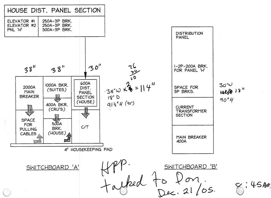
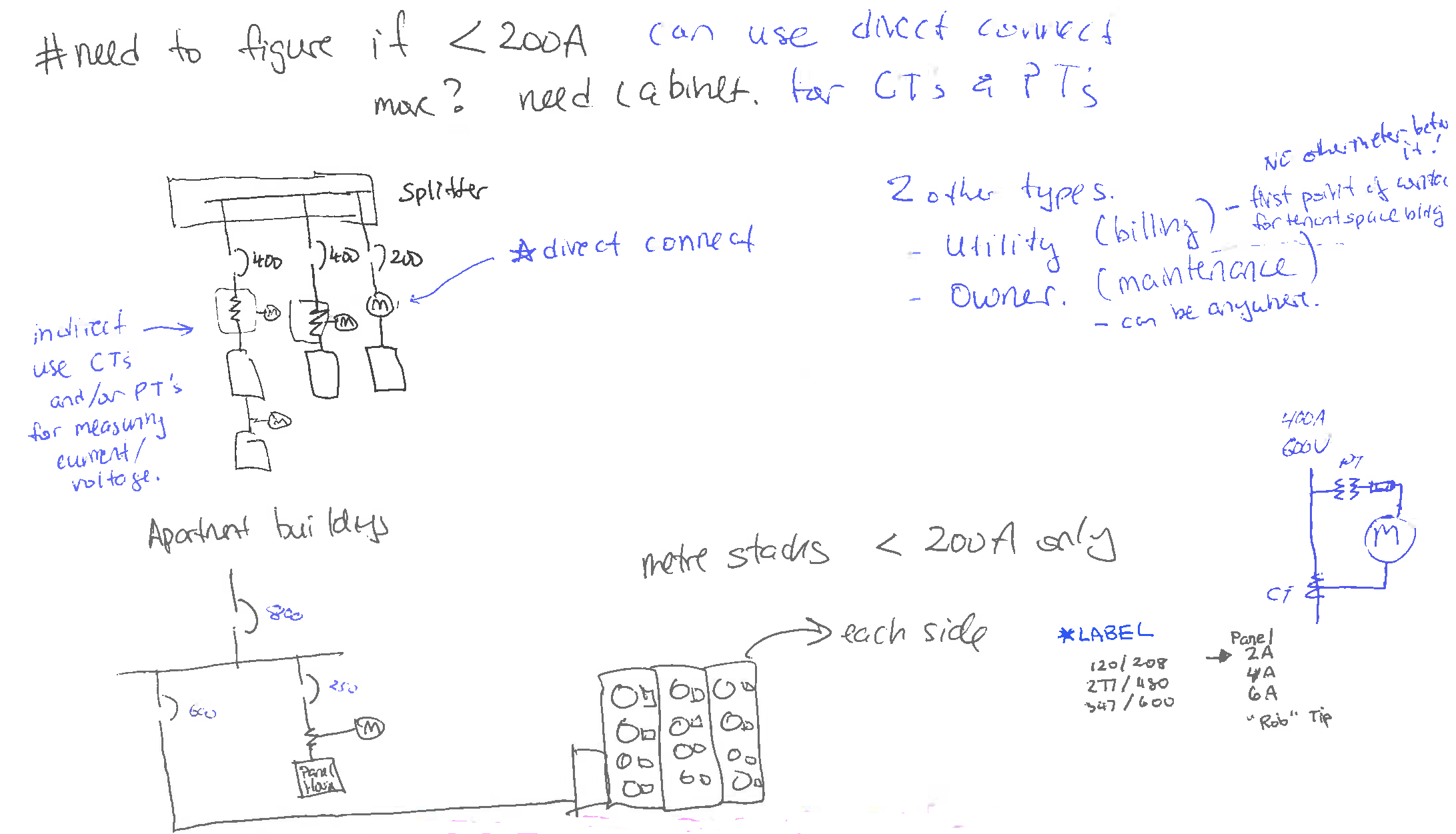
Switchboard & Metering
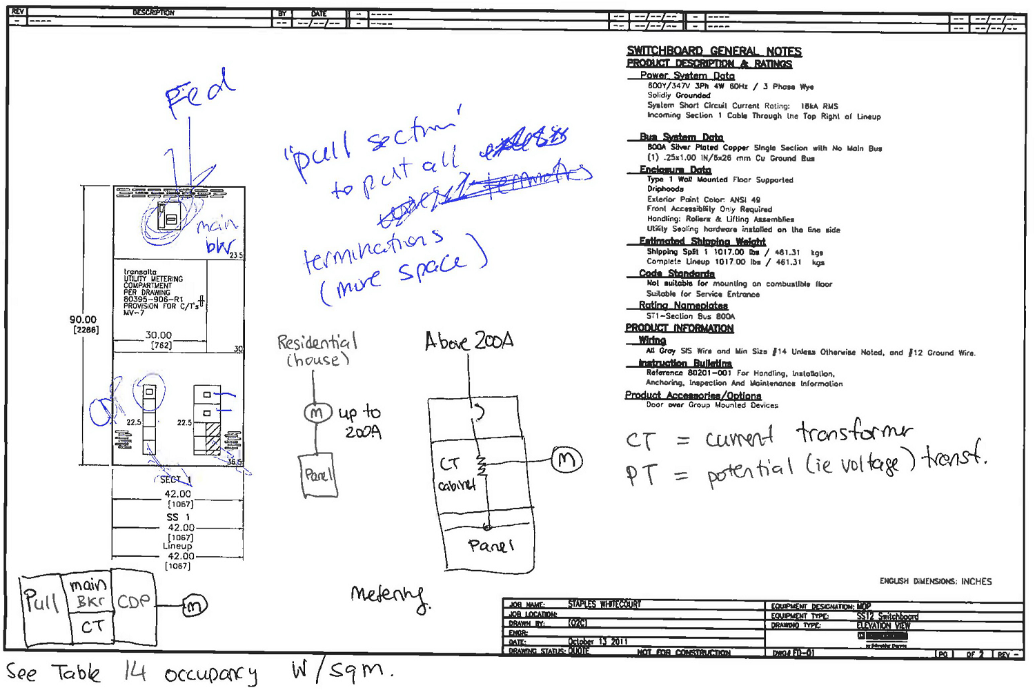
Inserting this into the SLD
How to draw splitter with
disconnect.
- ALWAYS splitter on TOP!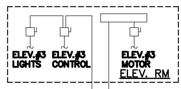
- place the
disconnect feeding in from the SIDE!! (think of how
disconnect is physically made)
- extend the feed to splitter.
- ESTHETICALLY place lines in halves,
thirds, etc.
- point to item it controls with
squiggle
- If it's the Panels in the same Room, there's no need for the breaker for Panel Feeding in.
Arc-Flash Study
Calculates the available incident energy at a location that can be released as an arc-flash. The result is a sticker that can be placed on the equipment at that location so that whoever works on that equipment energized can read that sticker to see what level of Personal Protective Equipment (PPE) they need to wear. In other words, this is to PROTECT PEOPLE.
Calculates the available fault current level at a location. The result is the size of the equipment including that equipment's withstand rated Amps Interrupting Capacity (AIC) level, so that the equipment can withstand a fault and not blow up. In other words, this is to PROTECT EQUIPMENT.
Issue for ?? / Revision Column /
STAMPS Tidbits
- IFC blah blah Issue for Construction
- Revision columns – based on other disciplines
- STAMPS – no stamps on drawings like Tittle Page aka “Non engineered” drawings.
Budget Analysis / Pricing Estimates
- use RSMeans
- note Location factor because of US Prices
- price / fixture
- Contingencies: in case things go awry, the factor to allow extra 5-10% budget
- Removing Underground Cabling - trench em out, might need to jackhammer concrete
THUS à take area of the trench TIMES the distance GIVES US volume to use in RS Means
Ex. 7” x 24” x 187 feet (just convert it to Cubic Yards)
RFS Reserve Fund Studies Tips and Tricks
ü Study drawings
ü Observe items on site via check list
ü Confirm Count # from site visit - Lights, Fire Alarm
ü Use spreadsheet with RS Means built in to estimate cost
ü Fire Alarm is calculated via square footage, typically found on ARCH
ü On Jen's Spreadsheet, round to the nearest $100
ü List main component categories, min $2000
ü Usually list as "Good" not excellent to be pessimistic
ü Organize by Defined Category # be Analytic
Cx (commissioning)
When copying and pasting forms:
- Under the "Submitted" Column, get info from shop drawings
1. DO THIS FIRST!!!! From Shop Drawings in the EQUIPMENT VERIFICATION
Reference = Device label
Description = General info
“Submitted” = Brand and model #
- Under the "Specified" column, take the closest resembling item
2. From Fixture/Equipment schedule (usually in prints) fill in Brand and model # for “Specified”
3. OPERATION VERIFICATION Insert All Room names
And then copy to other areas. Interior Lighting. Etc.
Edit/delete rooms from list – e.g. no exit lights in room, low voltage (fancy controls) or line voltage (regular) switching etc.